

System for measuring the geometry and profile of shafts and rotors
Home → Optical non-contact measurement systems → System for measuring the geometry and profile of shafts and rotors

It may be interesting for you:

PROBIUS UNO - Laser control equipment for the inside diameter and straightness of pipes
For diameters from 45 mm.
PROBIUS UNO...

Stator geometry and profile measuring instrument
Stator geometry and profile measuring instrument
...
The instrument for laser inspection of tubes, bars and small diameter barrels straightness
Device for laser control of straight pipe, rods...


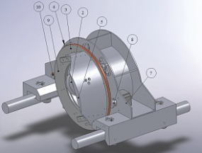
The measuring system on the basis of 2D laser scanner is designed to measure geometry of shafts of different shape. This system provides a three-dimensional model of the shaft with subsequent calculation of the exact radial section. The angle of the shaft inside the measuring frame does not affect the accuracy of measurement.
Rotation of the shaft is not required when the system is operating. The sensor rotates on precision circular linear guide.
Outgoing data is a file that contains the coordinates of the point cloud or the coordinates of points belonging to the section. The measurement system is completely self-contained.
System components:
Personal computer performs the secondary processing of point cloud and calculates the coordinates of points of the radial section of the product.
Gauge is a cylindrical shaft with a stepped diameter change and is intended for calibration of the measuring unit.
The calibration process is to scan a certain ring of the gauge corresponding to the configured measurement range. The subsequent analysis of angle transmitter readings and the profiles from 2D scanner allows to receive the calibration factors that determine the transmission ratio of the angle transmitter and the location of 2D scanner.
Prior to scanning the analyzed shaft is installed in CMM instead of the gauge, the measuring unit is moved to the point of control and the scanning process starts.
While scanning the disk, that is actuated by a stepper motor, makes one revolution around the product. Scanner receives the coordinates of the surface points of the shaft synchronously with the angle transmitter.
These data are streamed to the Ethernet interface on the PC. The axis of the resulting product model is calculated on the PC based on the axial symmetry of the product and the coordinates of the points of the axial section of the model are approximated.
Technical characteristics:
Diameter range of controlled products, mm
20...150
Measuring range in depth, mm
25
Measurement range along the axis, mm
22
The absolute error in determining
the coordinates of the point by the system, mm
±0.025(±0.02)